EP2423385A2 - Safety barrier for a safety device on a street and method for producing same - Google Patents
Safety barrier for a safety device on a street and method for producing same Download PDFInfo
- Publication number
- EP2423385A2 EP2423385A2 EP11178357A EP11178357A EP2423385A2 EP 2423385 A2 EP2423385 A2 EP 2423385A2 EP 11178357 A EP11178357 A EP 11178357A EP 11178357 A EP11178357 A EP 11178357A EP 2423385 A2 EP2423385 A2 EP 2423385A2
- Authority
- EP
- European Patent Office
- Prior art keywords
- section
- material thickness
- thickness
- guardrail
- protective barrier
- Prior art date
- Legal status (The legal status is an assumption and is not a legal conclusion. Google has not performed a legal analysis and makes no representation as to the accuracy of the status listed.)
- Granted
Links
- 238000004519 manufacturing process Methods 0.000 title claims abstract description 11
- 230000004888 barrier function Effects 0.000 title claims description 101
- 239000000463 material Substances 0.000 claims abstract description 105
- 238000000034 method Methods 0.000 claims abstract description 14
- 230000001681 protective effect Effects 0.000 claims description 77
- 230000007704 transition Effects 0.000 claims description 33
- 238000005096 rolling process Methods 0.000 claims description 27
- 229910052751 metal Inorganic materials 0.000 claims description 12
- 239000002184 metal Substances 0.000 claims description 12
- 230000008859 change Effects 0.000 claims description 2
- 238000010438 heat treatment Methods 0.000 description 4
- 230000008901 benefit Effects 0.000 description 3
- 230000007423 decrease Effects 0.000 description 3
- 230000003313 weakening effect Effects 0.000 description 3
- 229910000838 Al alloy Inorganic materials 0.000 description 2
- 238000013016 damping Methods 0.000 description 2
- 230000003247 decreasing effect Effects 0.000 description 2
- 229910000831 Steel Inorganic materials 0.000 description 1
- 239000011324 bead Substances 0.000 description 1
- 238000005452 bending Methods 0.000 description 1
- 239000002131 composite material Substances 0.000 description 1
- 239000002861 polymer material Substances 0.000 description 1
- 230000008569 process Effects 0.000 description 1
- 230000002787 reinforcement Effects 0.000 description 1
- 230000003014 reinforcing effect Effects 0.000 description 1
- 239000007787 solid Substances 0.000 description 1
- 239000010959 steel Substances 0.000 description 1
Images


Classifications
-
- E—FIXED CONSTRUCTIONS
- E01—CONSTRUCTION OF ROADS, RAILWAYS, OR BRIDGES
- E01F—ADDITIONAL WORK, SUCH AS EQUIPPING ROADS OR THE CONSTRUCTION OF PLATFORMS, HELICOPTER LANDING STAGES, SIGNS, SNOW FENCES, OR THE LIKE
- E01F15/00—Safety arrangements for slowing, redirecting or stopping errant vehicles, e.g. guard posts or bollards; Arrangements for reducing damage to roadside structures due to vehicular impact
- E01F15/02—Continuous barriers extending along roads or between traffic lanes
- E01F15/04—Continuous barriers extending along roads or between traffic lanes essentially made of longitudinal beams or rigid strips supported above ground at spaced points
- E01F15/0407—Metal rails
- E01F15/0423—Details of rails
Definitions
- the invention relates to a protective barrier for use on roads.
- Such guard rails are used as a continuous barrier along a road or between lanes to decelerate, return or stop vehicles off the roadway.
- the guardrails are usually attached to a post secured in the ground, or can also be connected together. To attach a guard rail to a post or two barriers together usually screw are used.
- a crash barrier post that includes a front support, a rearward slant support, and a footboard for connecting the front support to a foundation.
- a guardrail is fastened by means of flat head screws.
- the front support, the inclined support and the foot part are made of sheet metal and are produced by stamping and bending process.
- the foot is thick-walled than the front support and the diagonal support.
- the guide comprises a plurality of supports connected to the floor, to which an upper guardrail with the interposition of an L-shaped support member and a lower guardrail is attached via a damping element.
- the supports are connected to the longitudinal reinforcement via a tie rod.
- a method and apparatus for flexibly rolling a metal strip is known.
- the metal strip is guided for rolling by a nip formed between a first work roll and a second work roll.
- the size of the roll gap is varied in such a way that over the length of the metal strip, strip sections with a greater strip thickness and strip sections with a smaller strip thickness are achieved.
- guardrail which consists of extruded aluminum alloys and has different wall thicknesses across the width.
- the guardrail is weakened in the middle and reinforced at the top and bottom.
- the reinforced edges can be profiled by beads or designed in the form of a solid rounding.
- the spar of the road barrier has two channel-shaped parts which protrude against the roadway and are made thicker at the points which first absorb the impact. Also, the upper and lower edges are reinforced for stiffening.
- the surface consists on both sides of thin sheet metal, which is fixedly connected to a between the sheets arranged, in relation to the sheet thickness thick plastic layer.
- the guardrail is corrugated in cross-section. The thickness of the plastic layer in the region of the wave crest is greater than at the wave edges.
- a guardrail with a hollow profile having a smaller thickness than depth and a reinforcing wire extending longitudinally within the profile.
- a protective device for a road which has a fixed to the ground pillar, attached to this Leitholm strand of wooden Leitholmen and suspended below the Leitholmstrangs Leitblechstrang.
- the Leitblechstrang consists of substantially vertically extending, provided with away from the roadway oblique edge strips baffles.
- a plastic element is known as a protection device for motorcyclists.
- the plastic element comprises a molded of polymer material hollow body, which can be attached to existing crash barriers.
- the end portions of the plastic element have a reduced thickness, so that two juxtaposed plastic elements form a uniform profile.
- a movable guardrail which consists of a series of elements, each element is pivotally mounted centrally on a post.
- crash barriers A problem in the design of crash barriers is that the greatest burden of the crash barrier occurs when a vehicle collides with the bolted connections to the posts anchored in the ground. If the load is too high, the guardrails in the bolt holes can rip out due to bearing fatigue so that the vehicle can come off the road.
- the present invention is therefore based on the object to propose a safety barrier for a safety device on a road, which provides reliable protection against tearing of the guard rail from a post of the safety device and can be made at the same time with low material costs.
- the object is also to propose a corresponding method for producing such a protective barrier for a safety device.
- the solution consists in a protective barrier for a safety device on a road, comprising at least a first portion having a first material thickness and at least a second portion having a second material thickness, wherein the first material thickness is greater than the second material thickness.
- the at least one first section and the at least one second section are distributed over the length of the protective barrier or, in other words, that the protective barrier has a variable material thickness over the length.
- At least one first or second section means that two or more first sections or two or more second sections can also be provided on a safety barrier.
- the advantage of the protective barrier according to the invention is that it can be adjusted individually with respect to the material thickness over the length or over the width to the requirements in terms of strength or rigidity.
- the dimensioning of the individual sections of the guardrail can be done individually in the individual areas according to the respective loads, so that an oversizing of the guardrail is reduced.
- By deliberately reducing the thickness of the guardrail in low-load areas material can be saved, so that the guardrail ultimately without any loss in terms of mechanical properties has a low weight and thus can be produced inexpensively. It can be increased by flexible rolling and highly loaded areas of the guardrail with low manufacturing and material costs cost.
- the ratio between the thinner second material thickness and the thicker first material thickness is between 1/10 and 9/10, preferably between 1/3 or 1/2 as lower limit and 3/4 or 4/5 as upper limit, and is especially between 2/3 and 3/4.
- more than two sections with different material thickness are conceivable within a guardrail, for example, three or four sections of different thickness. This applies in particular to protective barriers with height of variable material thickness. If necessary, ratios between the thinnest material thickness and the thickest material thickness of less than 1/2 can be achieved.
- the material thickness of the one or more further sections is preferably smaller than that of the first section and larger than that of the second section.
- the protective barrier with a variable material thickness is preferably produced by flexible rolling of a metal strip.
- the material thickness is variable over a length of the protective barrier, so that first and second sections are distributed over the length of the protective barrier.
- the sections of different material thickness are arranged adjacent to one another in the longitudinal direction.
- the protective barrier has a lower material thickness along its length in low-load areas and a greater material thickness in areas subjected to higher loads so that they are purposefully reinforced.
- the material thickness over a width of the guardrail is variable, so first and second portions are distributed over the width.
- the sections of different material thickness are arranged adjacent to each other in the transverse direction.
- the protective barrier over its width in low-load areas on a lower material thickness and in higher-loaded areas a greater material thickness, so that they are purposefully reinforced.
- the material thickness is variable over the length and over the width of the guardrail.
- the protective barrier obtains a three-dimensional structure, wherein first longitudinal sections are provided with different material thickness, which are arranged adjacent to each other in the longitudinal direction, and at least one of the longitudinal sections in the transverse direction, that is over the width of the protective barrier, a plurality of width sections having different material thickness ,
- the latter embodiment achieves maximum flexibility with regard to the adaptability of the protective barrier to the stress.
- a transition section is provided in which the material thickness varies over the length or across the width. It is provided in particular that the material thickness decreases steadily in the transition section between the thicker first portion and the thinner second portion. If appropriate, it is also necessary to provide transition sections between the first or second section and one or more further sections.
- Each individual section preferably has an at least substantially constant wall thickness in the direction of extent of the respective section, that is to say in the longitudinal or in the transverse direction. Between two adjacent sections with approximately constant wall thickness, a transition section is provided in each case with a variable wall thickness in the direction of extent.
- the transition section has a shorter length, ie extension along the guardrail, as the thicker first section. Furthermore, it is preferably provided that the first section has a smaller length or extension along the protective barrier than the thinner second section.
- At least one first through-opening is provided in the first section or in at least one further section.
- This first passage opening is used in particular for attaching the guardrail to a post of the safety device.
- the attachment is preferably carried out by means of a screw, wherein a screw is inserted through the through hole of the guard rail and a corresponding hole in the post and bolted by a nut.
- the attachment of the guardrail to the post can also be done with the interposition of a damping element that can absorb part of the impact energy.
- the passage openings for attaching the guard rails are arranged on the post approximately centrally with respect to the width of the guardrail.
- the passage openings are designed in particular in the form of elongated holes. In principle, however, they can also have any other desired contour.
- a cross section through the first section or the further section, specifically in the region of the at least one first passage opening has a cross-sectional area which is at least one cross-sectional area of a cross section through the second section equivalent.
- the cross-sectional area of the cross-section through the guard rail in the region of the passage opening is equal to or greater than the cross-sectional area of the cross-section through the guard rail in a region which has no passage opening or other weakening zone.
- second passage openings are provided.
- the second passage openings may be arranged in the longitudinal direction at a distance from the first passage opening.
- a plurality of second passage openings can be provided over the width of the guardrail.
- the cross-sectional area prefferably corresponds to a cross-sectional area through the portion in which the second passage openings are arranged through the second section. This means that the cross-sectional area through the guard rail in the region of the second passage opening is equal to or greater than the cross-sectional area through the guard rail in the area which has no passage opening or other weakening zone.
- the protective barrier according to the invention forms a safety device.
- the posts are advantageously designed with a variable material thickness, which is preferably produced by flexible rolling of a metal strip.
- the advantages of the method according to the invention consist, as already explained above, in the fact that it is possible to produce safety barriers which, with respect to their material thickness, are adapted to the requirements with regard to the load in the event of an impact.
- the protective barriers according to the invention can withstand the same or higher loads as conventional protective barriers with a uniform material thickness, the weight and thus the costs being significantly reduced.
- the production of the different material thicknesses can take place according to a first possibility by means of flexible rolling, wherein over the length of the workpiece different material thicknesses are produced.
- strip profiling rolling of a sheet can be provided as method step. With the strip profile rolling, the material thickness of the sheet is changed across the width. In particular, this makes it possible to produce a protective barrier which has a greater material thickness in width sections in which one or more through holes are to be introduced than in width sections adjacent thereto in cross section.
- the strip profile rolling can be done before, during or after roll profiling or deep drawing.
- both a flexible rolling and a strip rolling can be performed. This creates a workpiece with variable wall thickness over the length and over the width. With the third possibility arises the greatest possible flexibility with regard to the design of the thickness ranges over the length or the width of the guardrail.
- a heat treatment is provided which can take place between or after the individual method steps.
- the guardrail is used in hard-rolling condition. This has a higher strength in the thin section or sections than in the thick sections.
- the non-heat-treated protective barrier is both thickness and strength optimized.
- FIGS. 1 to 4 will be described together below.
- a safety barrier 2 according to the invention for a safety device 3 which are mounted along roadways for motor vehicles and serve for protection if vehicles deviate from the roadway.
- individual guard rails 2 are detachably connected to each other and attached via posts 4 along a roadway.
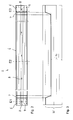
- FIG. 1 is a single guardrail 2, which may also be referred to as a guardrail, in perspective view and in FIG. 2 shown in side view.
- the protective barrier 2 is made of a steel material by forming.
- the protective barrier 2 comprises at its ends in each case a first section 5 with a first material thickness D5 and an intermediate second section 6 with a second material thickness D6, which is smaller than the material thickness D5 of the end-side first sections.
- a transition section 7 is formed in each case, in which the material thickness steadily decreases starting from the thicker section in the direction of the thinner section.
- the first section 5 extends over a length L5, the second section 6 over a length L6 and the transition section 7 over a length L7.
- the length L7 of the transition section 7 is shorter than the length L5 of the thicker first section 5.
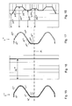
- FIG. 3 showing the thickness profile of the protective barrier 2 over the length, the ratio of the material thickness D6 of the thinner second portion 6 to the material thickness D5 of the thicker portion 5 is about 2 to 3, wherein here other thickness ratios would be conceivable, for example, between 1 to 2 to 4 to 5 can lie. Due to the variable thickness of the protective barrier 2 over the length of the guard rail 2 can be adjusted individually to the requirements in terms of strength or rigidity. It is understood that other thicknesses than the thickness profile shown are conceivable. For example, in addition to or as an alternative to the first sections 5, at the ends of the guardrail 2 are formed, also one or more thicker first portions are provided in the central region of the guardrail.
- the thickness profile of the guardrail is designed approximately wave-shaped, that is, that the material thickness decreases in each case from the thicker first sections, then reaches a minimum and increases again following the minimum towards the next thicker first section.
- the second section would be formed in the region of the minimum and shortened to a minimum length.
- the transition sections would be formed with a continuous change in thickness over the length correspondingly long.
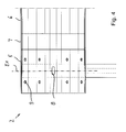
- the protective barrier 2 has distributed over its length a plurality of through holes 8, which are designed in particular in the form of slots. These passage openings 8 are arranged approximately centrally with respect to the width of the protective barrier 2 and serve for attaching the protective barrier 2 to a post 4, which in turn is anchored in the ground. The connection between the guardrail 2 and the post 4 via screw that are not shown here.
- the passage openings 8 are distributed at regular intervals over the length of the protective barrier 2. In each case, only a single first passage opening 8 is located in each cross-sectional plane.
- the material thickness D5 in the thicker first section 5, in which the first passage opening 8 is provided for attachment to the post 4, is in particular designed such that the cross-sectional area in a sectional plane E1 in which the first passage opening 8 is located, is equal to or greater than the cross-sectional area through the guard rail 2 in a plane E2, in which no passage opening is present.
- This embodiment results in a high rigidity or strength of the protective barrier 2 in the connection region, so that it is prevented in the event of an impact that the protective barrier 2 tears and is separated from the post 4 here.
- second through holes 9 are provided at the end portions of the guard rail 2.
- a plurality of second passage openings 9 are arranged distributed over the width of the guardrail 2. These second passage openings 9 serve for fastening two Guard rails 2 together. The attachment is usually done by means of screw. It can be seen that in the present case two rows of second through-openings 9 are provided at each end of the protective barrier 2, of which a first row lies on one side of the first through-opening 8 and a second row lies on the other side of the first through-opening 8.
- the cross-sectional area of the guardrail in a plane E3 in which the second passage openings 9 are arranged be equal to or greater than the cross-sectional area of the guard rail 2 in the plane E2 in which there are no holes or other weakening zones are provided. This results in the second through holes 9 sufficient strength of the guardrail 2, which prevents the guardrail 2 is torn in an impact of a motor vehicle.
- the present embodiment of the guard rail 2 with variable length material thickness is preferably made by flexibly rolling a sheet metal strip. After the flexible rolling, the sheet metal strip is cut to length according to the desired length and the passage openings for fixing the protective barrier 2 to a post 4 or more guard rails 2 are inserted into one another in the sheet metal.
- the contour of the protective barrier 2 is produced by roll profiling or deep drawing.
- a heat treatment can be provided as a further process step. The heat treatment can take place between or after the individual process steps.
- FIGS. 5 to 8 show a protective barrier 2 'according to the invention in a second embodiment. This corresponds in many parts to those according to the FIGS. 1 to 3 , so that reference is made to the above description in terms of similarities.
- the guardrail 2 'across the width has a variable material thickness, as best shown in FIGS FIGS. 7 and 8 can be seen, a section along the line VII-VII in FIG 6, and show the thickness over the width of the guardrail 2 '.
- the guardrail 2 ' is designed mirror-symmetrically with respect to the center plane M, which applies both in relation to the contour and with respect to the thickness profile.
- the protective barrier with respect to the plane M has an asymmetrical configuration of the thickness profile over the width.
- the profile of the guardrail in cross-section considered asymmetrical.
- the protective plank 2 " has a first section 11 with a first material thickness D11, which represents the largest material thickness of the protective plank 2" and can be, for example, 3 mm. Furthermore, a second section 12 with the smallest wall thickness D12 can be seen, which is formed on the outer edge of the protective plank 2 ", which can have, for example, a wall thickness of 2 mm.
- the material thickness in the transition section 13 which has a variable thickness D13 in the transverse direction, increases from the thickness D12 to the thickness D11 of the first section 11.
- the thickness profile of the transition section 13 is continuous.
- the first section 11 has a curved portion, which points in the assembled state in the direction of the roadway, and an adjoining straight portion which extends at an angle in the direction of the center plane.
- a bent section 14 with a significantly reduced thickness D14 follows.
- a transition section 17 with a wall thickness D17 increasing in the direction of the center plane M again adjoins the bent section 14.
- the transition portion 17 is relatively short, in particular shorter than the outer adjacent curved portion 14 or the inner adjoining central portion 16.
- the middle portion 16, which can also be referred to as the fourth section has the thickness D16. This is approximately the same as the largest thickness D11 of the first portion 11. It is understood that the central portion 16 may also have the thickness D11, as the first portion 11.
- the further course of the material thickness results from the symmetry of the protective barrier.
- the sections 11, 16 of greater material thickness alternate with the sections 12, 14 of smaller thickness. In each case, differently extended ramp-like transition sections 13, 15, 17 are arranged.
- the protective barrier 2 'according to the invention according to the present embodiment is preferably produced by means of strip profile rolling of a sheet. With the strip profile rolling, the material thickness of the sheet is changed across the width.
- the band profile rolling can be done before, during or after the roll profiling or deep drawing, with which the contour of the guardrail is generated.
- FIGS. 9 to 13 3 shows a third embodiment of a protective barrier 2 "according to the invention, in which the thickness of the material is varied both over the length and across the width
- the course of the thickness over the length with a middle second section 6 and two edge-side first sections 5 and Interposed transition regions 7 corresponds approximately to that in the FIG. 3 illustrated course.
- the three-dimensional structure of the material thickness over the protective barrier 2 "results from a combination of the thickness profiles according to the Figures 3 and 8th ,
- the present embodiment according to the FIGS. 9 to 13 a combination of the two embodiments mentioned above.
- the present embodiment has the thickest thickness profile across the width in the section 5 ", the corresponding cross section through the section 5" being in FIG FIG. 10 shown.
- the transverse section 11 within the longitudinal section 5 "of the transverse section 11 have a thickest material thickness of 3.0 mm, while the thinnest transverse section 12 may have a material thickness of 2.0.
- the second longitudinal section has the same thickness over the cross section, only at a slightly lower level.
- all sections 12 ', 13', 11 ', 15', 14 ', 17', 16 'of the second longitudinal section 6 have a slightly smaller material thickness D12', D13 ', D11', D15 ', D14', D17 ', D16' as the corresponding sections 12, 13, 11, 15, 14, 17, 16 of the first longitudinal section 5 ".
- the thickness difference may be 0.5 to 1.0 mm, for example.
- a corresponding ramp-like transition takes place between the respectively longitudinally adjacent longitudinal sections 12, 12 ', 13, 13', etc.
- the production of the protective barrier 2 is effected by the combination of the method steps of flexible rolling, by means of which a band with variable wall thickness is produced with thicker first sections 5, transition sections 7 and thinner second sections 6, and strip profile rollers, by means of which subsequently sections 11, 12, 13, 14, 15, 16, 17 are produced over the width of different thickness.
- FIGS. 14 to 18 There is shown a fourth embodiment of a protective barrier 2 '"according to the invention, in which the thickness of the material is varied over both the length and the width FIGS. 9 to 13 so that in terms of the similarities to the above description, and thus to the description of the FIGS. 1 to 8 Reference can be made.
- the course of the thickness over the length with a middle second portion 6 '"and two edge-side first portions 5'" and arranged therebetween transition regions 7 '" corresponds approximately to that in the FIG. 3 illustrated course.
- the variation of the thickness across the width of the guardrail 2 '"in the second section 6'" corresponds to that in the FIG. 8 illustrated course. This is represented by the specification of sections with the thicknesses D11 to D17. The respective sections extend along the guardrail 2 "', over the second section 6"'.
- the present embodiment has the thickest thickness profile across the width in the section 5 " FIG. 10 , which shows a cross-section through the section 5 '", recognizable that the protective barrier 2'" here over the entire width of a constant maximum thickness D5 "'. That is, the individual transverse sections 12", 13 “, 11", 15 “, 14", 17 “and 16” all have the same thickness D5 "', which may be 3.0 mm, for example.
- the guardrail 2 '" has in the second section 6''' the same thickness profile over the cross section, as in the embodiment according to the FIGS. 5 to 8 ,
- a corresponding ramp-like transition takes place between the respectively longitudinally adjacent sections 12", 13 ", etc. of the first longitudinal section 5 '''and the corresponding sections 12'',13'', etc. of the second longitudinal section 6''.
- the production of the protective barrier 2 " is effected by the combination of the method steps flexible rolling, by means of which a band over the length of variable wall thickness with thicker first sections 5, transition sections 7 and thinner second sections 6 is generated, and strip profile rollers, by means of the subsequently in the second longitudinal section
- the sections 11 "', 12"', 13 “', 14"', 15 “', 16"', 17 “'with over the width of different thickness are produced.
- the embodiments shown are only exemplary in terms of the thickness profiles over the length or the width. Of course, other thickness profiles over the length or over the width are conceivable.
- another protective barrier could also be designed such that in the first section 5 it has a profile with a width which is variable over the width, as shown in FIG. 8 is shown, and in the second section 6 has a constant thickness over the width, as in the embodiment according to the FIGS. 1 to 4 , A transition section 7 would connect the thicknesses of the first and second sections accordingly.
- the ratio between the thinner second material thickness and the thicker first material thickness may be between 1/10 and 9/10, preferably between 1/3 and 4/5 or 1/2 and 4/5, and is in particular between 1/3 and 3 / 4, or between 2/3 and 3/4.
- All of the protective barriers according to the invention described above have the advantage that they can be adapted individually with respect to the material thickness over the length or over the width to the requirements in terms of strength or rigidity.
Abstract
Description
Die Erfindung betrifft eine Schutzplanke zum Einsatz an Straßen. Derartige Schutzplanken werden als durchlaufende Sperre entlang einer Straße oder zwischen Fahrspuren verwendet, um von der Fahrbahn abkommende Fahrzeuge abzubremsen, zurückzuleiten oder zu stoppen. Die Schutzplanken werden üblicherweise an einem im Boden befestigten Pfosten angebracht, oder können auch miteinander verbunden werden. Zur Befestigung einer Schutzplanke an einem Pfosten oder zweier Schutzplanken miteinander werden üblicherweise Schraubverbindungen verwendet.The invention relates to a protective barrier for use on roads. Such guard rails are used as a continuous barrier along a road or between lanes to decelerate, return or stop vehicles off the roadway. The guardrails are usually attached to a post secured in the ground, or can also be connected together. To attach a guard rail to a post or two barriers together usually screw are used.
Aus der
Aus der
Aus der
Aus der
Aus der
Aus der
Aus der
Aus der
Aus der
Aus der
Aus der
Problematisch bei der Gestaltung von Schutzplanken ist, dass die größte Belastung der Schutzplanken beim Aufprall eines Fahrzeugs im Bereich der Anschraubverbindungen zu den im Boden verankerten Pfosten auftritt. Bei zu hoher Belastung können die Schutzplanken in den Anschraublöchern durch Lochleibung ausreißen, so dass das Fahrzeug von der Fahrbahn abkommen kann.A problem in the design of crash barriers is that the greatest burden of the crash barrier occurs when a vehicle collides with the bolted connections to the posts anchored in the ground. If the load is too high, the guardrails in the bolt holes can rip out due to bearing fatigue so that the vehicle can come off the road.
Der vorliegenden Erfindung liegt daher die Aufgabe zugrunde, eine Schutzplanke für eine Sicherheitseinrichtung an einer Straße vorzuschlagen, die einen zuverlässigen Schutz gegen Ausreißen der Schutzplanke von einem Pfosten der Sicherheitseinrichtung bietet und die gleichzeitig mit geringem Materialaufwand hergestellt werden kann. Die Aufgabe besteht ferner darin, ein entsprechendes Verfahren zur Herstellung einer solchen Schutzplanke für eine Sicherheitseinrichtung vorzuschlagen.The present invention is therefore based on the object to propose a safety barrier for a safety device on a road, which provides reliable protection against tearing of the guard rail from a post of the safety device and can be made at the same time with low material costs. The object is also to propose a corresponding method for producing such a protective barrier for a safety device.
Die Lösung besteht in einer Schutzplanke für eine Sicherheitseinrichtung an einer Straße, umfassend zumindest einen ersten Abschnitt mit einer ersten Materialdicke und zumindest einen zweiten Abschnitt mit einer zweiten Materialdicke, wobei die erste Materialdicke größer ist als die zweite Materialdicke. Es ist insbesondere vorgesehen, dass der zumindest eine erste Abschnitt und der zumindest eine zweite Abschnitt über der Länge der Schutzplanke verteilt angeordnet sind oder, mit anderen Worten, dass die Schutzplanke eine variable Materialdicke über der Länge aufweist. Zumindest ein erster bzw. zweiter Abschnitt bedeutet, dass auch zwei oder mehr erste Abschnitte bzw. zwei oder mehr zweite Abschnitte an einer Schutzplanke vorgesehen sein können.The solution consists in a protective barrier for a safety device on a road, comprising at least a first portion having a first material thickness and at least a second portion having a second material thickness, wherein the first material thickness is greater than the second material thickness. In particular, it is provided that the at least one first section and the at least one second section are distributed over the length of the protective barrier or, in other words, that the protective barrier has a variable material thickness over the length. At least one first or second section means that two or more first sections or two or more second sections can also be provided on a safety barrier.
Der Vorteil der erfindungsgemäßen Schutzplanke besteht darin, dass diese hinsichtlich der Materialdicke über der Länge bzw. über der Breite individuell an die Anforderungen in Bezug auf die Festigkeit bzw. Steifigkeit angepasst werden kann. Die Dimensionierung der einzelnen Abschnitte der Schutzplanke kann in den einzelnen Bereichen nach den jeweiligen Belastungen individuell erfolgen, so dass eine Überdimensionierung der Schutzplanke reduziert wird. Durch gezielte Reduktion der Dicke der Schutzplanke in geringer belasteten Bereichen kann Material eingespart werden, so dass die Schutzplanke letztlich ohne Einbußen in Bezug auf die mechanischen Eigenschaften ein geringes Gewicht aufweist und somit kostengünstig hergestellt werden kann. Es lassen sich durch flexibles Walzen auch hoch belastete Bereiche der Schutzplanke mit geringem Fertigungs- und Materialaufwand kostengünstig verstärken.The advantage of the protective barrier according to the invention is that it can be adjusted individually with respect to the material thickness over the length or over the width to the requirements in terms of strength or rigidity. The dimensioning of the individual sections of the guardrail can be done individually in the individual areas according to the respective loads, so that an oversizing of the guardrail is reduced. By deliberately reducing the thickness of the guardrail in low-load areas material can be saved, so that the guardrail ultimately without any loss in terms of mechanical properties has a low weight and thus can be produced inexpensively. It can be increased by flexible rolling and highly loaded areas of the guardrail with low manufacturing and material costs cost.
Nach einer bevorzugten Ausgestaltung liegt das Verhältnis zwischen der dünneren zweiten Materialdicke und der dickeren ersten Materialdicke zwischen 1/10 und 9/10, vorzugsweise zwischen 1/3 oder 1/2 als Untergrenze und 3/4 oder 4/5 als Obergrenze, und liegt insbesondere zwischen 2/3 und 3/4. Dabei sind innerhalb einer Schutzplanke prinzipiell auch mehr als zwei Abschnitte mit unterschiedlicher Materialdicke denkbar, beispielsweise drei oder vier Abschnitte mit unterschiedlicher Dicke. Dies gilt insbesondere für Schutzplanken mit über der Höhe variabler Materialdicke. Dabei können gegebenenfalls Verhältnisse zwischen der dünnsten Materialdicke und der dicksten Materialdicke von weniger als 1/2 erreicht werden. Bei Verwendung von mehr als zwei Abschnitten mit unterschiedlicher Materialdicke ist die Materialdicke der ein oder mehreren weiteren Abschnitte vorzugsweise jeweils kleiner als die des ersten Abschnitts und größer ist als die des zweiten Abschnitts. Die Schutzplanke mit einer variablen Materialdicke ist vorzugsweise durch flexibles Walzen eines Blechbandes hergestellt.According to a preferred embodiment, the ratio between the thinner second material thickness and the thicker first material thickness is between 1/10 and 9/10, preferably between 1/3 or 1/2 as lower limit and 3/4 or 4/5 as upper limit, and is especially between 2/3 and 3/4. In principle, more than two sections with different material thickness are conceivable within a guardrail, for example, three or four sections of different thickness. This applies in particular to protective barriers with height of variable material thickness. If necessary, ratios between the thinnest material thickness and the thickest material thickness of less than 1/2 can be achieved. When using more than two sections with different material thickness, the material thickness of the one or more further sections is preferably smaller than that of the first section and larger than that of the second section. The protective barrier with a variable material thickness is preferably produced by flexible rolling of a metal strip.
Nach einer ersten bevorzugten Ausführungsform ist vorgesehen, dass die Materialdicke über eine Länge der Schutzplanke variabel ist, erste und zweite Abschnitte also über die Länge der Schutzplanke verteilt angeordnet sind. Das bedeutet, dass die Abschnitte mit unterschiedlicher Materialdicke in Längsrichtung benachbart zueinander angeordnet sind. Dabei weist die Schutzplanke über ihre Länge in geringer belasteten Bereichen eine niedrigere Materialdicke auf und in höher belasteten Bereichen eine größere Materialdicke, so dass diese gezielt verstärkt sind.According to a first preferred embodiment, it is provided that the material thickness is variable over a length of the protective barrier, so that first and second sections are distributed over the length of the protective barrier. This means that the sections of different material thickness are arranged adjacent to one another in the longitudinal direction. In this case, the protective barrier has a lower material thickness along its length in low-load areas and a greater material thickness in areas subjected to higher loads so that they are purposefully reinforced.
Nach einer zweiten bevorzugten Ausführungsform ist vorgesehen, dass die Materialdicke über eine Breite der Schutzplanke, das heißt quer zur Längserstreckung, variabel ist, erste und zweite Abschnitte also über die Breite verteilt angeordnet sind. Das bedeutet, dass die Abschnitte mit unterschiedlicher Materialdicke in Querrichtung benachbart zueinander angeordnet sind. Dabei weist die Schutzplanke über ihre Breite in geringer belasteten Bereichen eine niedrigere Materialdicke auf und in höher belasteten Bereichen eine größere Materialdicke, so dass diese gezielt verstärkt sind.According to a second preferred embodiment, it is provided that the material thickness over a width of the guardrail, that is transversely to the longitudinal extent, is variable, so first and second portions are distributed over the width. This means that the sections of different material thickness are arranged adjacent to each other in the transverse direction. In this case, the protective barrier over its width in low-load areas on a lower material thickness and in higher-loaded areas a greater material thickness, so that they are purposefully reinforced.
Nach einer dritten bevorzugten Ausführungsform, die eine Kombination der ersten und zweiten Möglichkeit darstellt, ist ferner vorgesehen, dass die Materialdicke über der Länge und über der Breite der Schutzplanke variabel ist. Das bedeutet, dass die Schutzplanke eine dreidimensionale Struktur erhält, wobei erste Längsabschnitte mit unterschiedlicher Materialdicke vorgesehen sind, die in Längsrichtung benachbart zueinander angeordnet sind, und zumindest einer der Längsabschnitte in Querrichtung, das heißt über der Breite der Schutzplanke, mehrere Breitenabschnitte mit unterschiedlicher Materialdicke aufweist. Durch die letztgenannte Ausführungsform wird ein Höchstmaß an Flexibilität hinsichtlich der Anpassbarkeit der Schutzplanke an die Beanspruchung erreicht.According to a third preferred embodiment, which represents a combination of the first and second possibilities, it is further provided that the material thickness is variable over the length and over the width of the guardrail. This means that the protective barrier obtains a three-dimensional structure, wherein first longitudinal sections are provided with different material thickness, which are arranged adjacent to each other in the longitudinal direction, and at least one of the longitudinal sections in the transverse direction, that is over the width of the protective barrier, a plurality of width sections having different material thickness , The latter embodiment achieves maximum flexibility with regard to the adaptability of the protective barrier to the stress.
Nach einer bevorzugten Ausgestaltung, die für alle der obengenannten Ausführungsformen gilt, ist zwischen jeweils zwei Abschnitten mit unterschiedlicher Materialdicke ein Übergangsabschnitt vorgesehen, in dem die Materialdicke über der Länge bzw. über der Breite variiert. Dabei ist insbesondere vorgesehen, dass die Materialdicke im Übergangsabschnitt zwischen dem dickeren ersten Abschnitt und dem dünneren zweiten Abschnitt stetig abnimmt. Es sind gegebenenfalls auch Übergangsabschnitte zwischen dem ersten bzw. zweiten Abschnitt und einem oder mehreren weiteren Abschnitten vorzusehen. Jeder einzelne Abschnitt hat vorzugsweise eine zumindest im wesentlichen gleichbleibende Wandstärke in Erstreckungsrichtung des jeweiligen Abschnitts, das heißt in Längs- oder in Querrichtung. Zwischen zwei benachbarten Abschnitten mit etwa konstanter Wanddicke ist jeweils ein Übergangsabschnitt mit veränderlicher Wanddicke in Erstreckungsrichtung vorgesehen.According to a preferred embodiment, which applies to all of the above-mentioned embodiments, is between in each case two sections with different material thickness a transition section is provided in which the material thickness varies over the length or across the width. It is provided in particular that the material thickness decreases steadily in the transition section between the thicker first portion and the thinner second portion. If appropriate, it is also necessary to provide transition sections between the first or second section and one or more further sections. Each individual section preferably has an at least substantially constant wall thickness in the direction of extent of the respective section, that is to say in the longitudinal or in the transverse direction. Between two adjacent sections with approximately constant wall thickness, a transition section is provided in each case with a variable wall thickness in the direction of extent.
Für die obengenannte erste Ausführungsform mit über der Länge variabler Dicke der Schutzplanke gilt vorzugsweise, dass der Übergangsabschnitt eine geringere Länge, also Ausdehnung entlang der Schutzplanke aufweist, als der dickere erste Abschnitt. Weiter ist vorzugsweise vorgesehen, dass der erste Abschnitt eine geringere Länge, bzw. Ausdehnung entlang der Schutzplanke aufweist, als der dünnere zweite Abschnitt.For the above-mentioned first embodiment with over the length of variable thickness of the guardrail is preferably that the transition section has a shorter length, ie extension along the guardrail, as the thicker first section. Furthermore, it is preferably provided that the first section has a smaller length or extension along the protective barrier than the thinner second section.
Nach einer bevorzugten Ausgestaltung, die für alle der obengenannten Ausführungsformen gilt, ist im ersten Abschnitt oder in zumindest einem weiteren Abschnitt zumindest eine erste Durchgangsöffnung vorgesehen. Diese erste Durchgangsöffnung dient insbesondere zum Befestigen der Schutzplanke an einem Pfosten der Sicherheitseinrichtung. Die Befestigung erfolgt dabei vorzugsweise mittels einer Schraubverbindung, wobei eine Schraube durch die Durchgangsöffnung der Schutzplanke und eine entsprechende Bohrung im Pfosten hindurchgesteckt und mittels einer Mutter verschraubt wird. Dabei kann die Befestigung der Schutzplanke an dem Pfosten auch unter Zwischenschaltung eines Dämpfungselements erfolgen, dass einen Teil der Aufprallenergie absorbieren kann. Üblicherweise sind die Durchgangsöffnungen zum Anbringen der Schutzplanken am Pfosten etwa mittig in Bezug auf die Breite der Schutzplanke angeordnet. Die Durchgangsöffnungen sind insbesondere in Form von Langlöchern gestaltet. Sie können prinzipiell jedoch auch eine beliebig andere Kontur aufweisen.According to a preferred embodiment, which applies to all of the abovementioned embodiments, at least one first through-opening is provided in the first section or in at least one further section. This first passage opening is used in particular for attaching the guardrail to a post of the safety device. The attachment is preferably carried out by means of a screw, wherein a screw is inserted through the through hole of the guard rail and a corresponding hole in the post and bolted by a nut. In this case, the attachment of the guardrail to the post can also be done with the interposition of a damping element that can absorb part of the impact energy. Usually, the passage openings for attaching the guard rails are arranged on the post approximately centrally with respect to the width of the guardrail. The passage openings are designed in particular in the form of elongated holes. In principle, however, they can also have any other desired contour.
Für eine hohe Steifigkeit bzw. Festigkeit der Schutzplanke ist es günstig, wenn ein Querschnitt durch den ersten Abschnitt bzw. den weiteren Abschnitt, und zwar im Bereich der zumindest einen ersten Durchgangsöffnung, eine Querschnittsfläche aufweist, welche wenigstens einer Querschnittsfläche eines Querschnitts durch den zweiten Abschnitt entspricht. Das bedeutet, dass die Querschnittsfläche des Querschnitts durch die Schutzplanke im Bereich der Durchgangsöffnung gleich groß oder größer der Querschnittsfläche des Querschnitts durch die Schutzplanke in einem Bereich ist, der keine Durchgangsöffnung oder andere Schwächungszone aufweist. Dies gilt sowohl für die Ausführungsform mit über der Länge der Schutzplanke variabler Dicke, als auch für die Ausführungsform mit über der Breite der Schutzplanke variabler Dicke, als auch für die Kombination aus beiden Ausführungsformen.For a high rigidity or strength of the protective barrier, it is advantageous if a cross section through the first section or the further section, specifically in the region of the at least one first passage opening, has a cross-sectional area which is at least one cross-sectional area of a cross section through the second section equivalent. This means that the cross-sectional area of the cross-section through the guard rail in the region of the passage opening is equal to or greater than the cross-sectional area of the cross-section through the guard rail in a region which has no passage opening or other weakening zone. This applies both to the embodiment with over the length of the protective barrier of variable thickness, as well as for the embodiment with the width of the protective barrier of variable thickness, as well as for the combination of both embodiments.
Dies gilt vorzugsweise auch für weitere Abschnitte der Schutzplanke, in denen weitere, zweite Durchgangsöffnungen vorgesehen sind. Die zweiten Durchgangsöffnungen können in Längsrichtung mit Abstand zu der ersten Durchgangsöffnung angeordnet sein. Dabei können insbesondere mehrere zweite Durchgangsöffnungen über der Breite der Schutzplanke vorgesehen sein. Diese zweiten Durchgangsöffnungen dienen insbesondere zum Verbinden zweier Schutzplanken miteinander. Dabei erfolgt die Verbindung vorzugsweise mittels Schraubverbindungen.This preferably also applies to further sections of the protective barrier, in which further, second passage openings are provided. The second passage openings may be arranged in the longitudinal direction at a distance from the first passage opening. In this case, in particular a plurality of second passage openings can be provided over the width of the guardrail. These second passage openings are used in particular for connecting two guard rails together. The connection is preferably carried out by means of screw.
Bezüglich der zweiten Durchgangsöffnungen gilt vorzugsweise ebenfalls, dass die Querschnittsfläche durch den Abschnitt, in dem die zweiten Durchgangsöffnungen angeordnet sind, einer Querschnittsfläche durch den zweiten Abschnitt wenigstens entspricht. Das bedeutet, dass die Querschnittsfläche durch die Schutzplanke im Bereich der zweiten Durchgangsöffnung gleich groß oder größer der Querschnittsfläche durch die Schutzplanke in dem Bereich ist, der keine Durchgangsöffnung oder andere Schwächungszone aufweist.With regard to the second passage openings, it is also preferable for the cross-sectional area to at least correspond to a cross-sectional area through the portion in which the second passage openings are arranged through the second section. This means that the cross-sectional area through the guard rail in the region of the second passage opening is equal to or greater than the cross-sectional area through the guard rail in the area which has no passage opening or other weakening zone.
Zusammen mit einem oder mehreren Pfosten bildet die erfindungsgemäße Schutzplanke eine Sicherheitseinrichtung. Bei einer solchen Sicherheitseinrichtung sind vorteilhafterweise auch die Pfosten mit einer variablen Materialdicke ausgeführt, welche vorzugsweise durch flexibles Walzen eines Blechbandes hergestellt wird.Together with one or more posts, the protective barrier according to the invention forms a safety device. In such a safety device, the posts are advantageously designed with a variable material thickness, which is preferably produced by flexible rolling of a metal strip.
Die Lösung der obengenannten Aufgabe besteht weiter in einem Verfahren zum Herstellen einer Schutzplanke für eine Sicherheitseinrichtung an einer Straße mit folgenden Verfahrensschritten:
- Walzen eines Bleches, wobei erste Abschnitte mit einer ersten Materialdicke und zweite Abschnitte mit einer zweiten Materialdicke über eine Erstreckungsrichtung der Schutzplanke erzeugt werden, wobei die erste Materialdicke größer ist als die zweite Materialdicke. Die Erzeugung der Kontur der Schutzplanke kann durch Rollprofilieren oder Tiefziehen erfolgen. Vorzugsweise erfolgt ein Einbringen von zumindest einer Durchgangsöffnung in die Schutzplanke in einem Abschnitt mit größerer Materialdicke, insbesondere im ersten Abschnitt.
- Rolling a sheet, wherein first portions are produced with a first material thickness and second portions with a second material thickness over a direction of extension of the protective barrier, wherein the first material thickness is greater than the second material thickness. The generation of the contour of the guardrail can be done by roll profiling or deep drawing. Preferably, at least one passage opening is introduced into the guardrail in a section of greater material thickness, in particular in the first section.
Die Vorteile des erfindungsgemäßen Verfahrens bestehen, wie oben bereits erläutert, darin, dass sich Schutzplanken herstellen lassen, die hinsichtlich ihrer Materialdicke an die Anforderungen in Bezug auf die Belastung bei einem Aufprall angepasst sind. Unter optimaler Ausnutzung des eingesetzten Materials können die erfindungsgemäß hergestellten Schutzplanken denselben oder höheren Belastungen standhalten, wie herkömmliche Schutzplanken mit einheitlicher Materialstärke, wobei das Gewicht und damit die Kosten deutlich reduziert sind.The advantages of the method according to the invention consist, as already explained above, in the fact that it is possible to produce safety barriers which, with respect to their material thickness, are adapted to the requirements with regard to the load in the event of an impact. With optimum utilization of the material used, the protective barriers according to the invention can withstand the same or higher loads as conventional protective barriers with a uniform material thickness, the weight and thus the costs being significantly reduced.
Die Erzeugung der unterschiedlichen Materialstärken kann nach einer ersten Möglichkeit mittels flexiblem Walzen erfolgen, wobei über der Länge des Werkstücks unterschiedliche Materialdicken erzeugt werden. Nach einer alternativen oder ergänzenden Möglichkeit kann als Verfahrensschritt Bandprofilwalzen eines Bleches vorgesehen sein. Mit dem Bandprofilwalzen wird die Materialdicke des Bleches über der Breite verändert. Hiermit lässt sich insbesondere eine Schutzplanke herstellen, die in Breitenabschnitten, in denen ein oder mehrere Durchgangslöcher einzubringen sind, eine größere Materialdicke aufweist, als in hierzu im Querschnitt benachbarten Breitenabschnitten. Das Bandprofilwalzen kann vor, während oder nach dem Rollprofilieren oder Tiefziehen erfolgen.The production of the different material thicknesses can take place according to a first possibility by means of flexible rolling, wherein over the length of the workpiece different material thicknesses are produced. According to an alternative or additional possibility, strip profiling rolling of a sheet can be provided as method step. With the strip profile rolling, the material thickness of the sheet is changed across the width. In particular, this makes it possible to produce a protective barrier which has a greater material thickness in width sections in which one or more through holes are to be introduced than in width sections adjacent thereto in cross section. The strip profile rolling can be done before, during or after roll profiling or deep drawing.
Nach einer dritten Möglichkeit kann sowohl ein flexibles Walzen als auch ein Bandprofilwalzen durchgeführt werden. Hiermit wird ein Werkstück mit über der Länge und über der Breite variabler Wandstärke erzeugt. Mit der dritten Möglichkeit ergibt sich die größtmögliche Flexibilität hinsichtlich der Ausgestaltung der Dickenbereiche über der Länge bzw. der Breite der Schutzplanke.After a third possibility, both a flexible rolling and a strip rolling can be performed. This creates a workpiece with variable wall thickness over the length and over the width. With the third possibility arises the greatest possible flexibility with regard to the design of the thickness ranges over the length or the width of the guardrail.
Nach einer möglichen Ausgestaltung ist als weiterer Verfahrensschritt zur Herstellung der Schutzplanke eine Wärmebehandlung vorgesehen, die zwischen oder nach den einzelnen Verfahrensschritten erfolgen kann. Es ist jedoch auch denkbar, dass nach dem flexiblen Walzen, nach dem Bandprofilwalzen oder dem Rollprofilieren keine Wärmebehandlung durchgeführt wird, sondern dass die Schutzplanke in walzhartem Zustand eingesetzt wird. Diese weist im dünnen Abschnitt bzw. den dünnen Abschnitten eine höhere Festigkeit auf als in dem bzw. den dicken Abschnitten. Insofern ist die nicht wärmebehandelte Schutzplanke gleichzeitig dicken- als auch festigkeitsoptimiert.According to a possible embodiment, as a further method step for the production of the protective barrier, a heat treatment is provided which can take place between or after the individual method steps. However, it is also conceivable that after the flexible rolling, after the strip profile rolling or roll profiling no heat treatment is performed, but that the guardrail is used in hard-rolling condition. This has a higher strength in the thin section or sections than in the thick sections. In this respect, the non-heat-treated protective barrier is both thickness and strength optimized.
Bevorzugte Ausführungsformen werden nachstehend anhand der Zeichnungsfiguren erläutert. Hierin zeigt:
Figur 1- eine erfindungsgemäße Schutzplanke in einer ersten Ausführungsform mit über der Länge variabler Materialdicke in perspektivischer Ansicht;
Figur 2- die
Schutzplanke nach Figur 1 in Seitenansicht; - Figur 3
- den Verlauf der Materialdicke der Schutzplanke nach
Figur 1 über der Länge; - Figur 4
- den Bereich, an dem die
Schutzplanke nach Figur 1 an einem Pfosten befestigt ist, im Detail; Figur 5- eine erfindungsgemäße Schutzplanke in einer zweiten Ausführungsform mit über der Breite variabler Materialdicke in perspektivischer Ansicht;
Figur 6- einen Teilabschnitt der Schutzplanke nach
Figur 5 ; Figur 7- die
Schutzplanke nach Figur 5 im Querschnitt gemäß Schnittlinie VII-VII aus Figur 6 ; Figur 8- den Dickenverlauf der Schutzplanke nach
Figur 5 über der Breite; Figur 9- eine erfindungsgemäße Schutzplanke in einer dritten Ausführungsform mit über der Länge und über der Breite variabler Materialdicke in perspektivischer Ansicht;
- Figur 10
- die
Schutzplanke nach Figur 9 im Querschnitt durch den ersten Abschnitt; Figur 11- den Dickenverlauf der Schutzplanke nach
Figur 10 im ersten Abschnitt über der Breite; Figur 12- die
Schutzplanke nach Figur 9 im Querschnitt durch den zweiten Abschnitt; Figur 13- den Dickenverlauf der Schutzplanke nach
Figur 10 im zweiten Abschnitt über der Breite; Figur 14- eine erfindungsgemäße Schutzplanke in einer vierten Ausführungsform mit über der Länge und über der Breite variabler Materialdicke in perspektivischer Ansicht;
Figur 15- die
Schutzplanke nach Figur 14 in einem Querschnitt durch den ersten Abschnitt; Figur 16- den Dickenverlauf der Schutzplanke nach
Figur 15 im ersten Abschnitt über der Breite; Figur 17- die
Schutzplanke nach Figur 14 in einem Querschnitt durch den zweiten Abschnitt; und - Figur 18
- den Dickenverlauf der Schutzplanke nach
Figur 15 im zweiten Abschnitt über der Breite.
- FIG. 1
- a protective barrier according to the invention in a first embodiment with over the length of variable material thickness in a perspective view;
- FIG. 2
- the protective barrier after
FIG. 1 in side view; - FIG. 3
- the course of the material thickness of the guardrail after
FIG. 1 over the length; - FIG. 4
- the area where the guard rail after
FIG. 1 attached to a post, in detail; - FIG. 5
- a protective barrier according to the invention in a second embodiment with over the width variable material thickness in a perspective view;
- FIG. 6
- a subsection of the protective barrier after
FIG. 5 ; - FIG. 7
- the protective barrier after
FIG. 5 in cross section according to section line VII-VIIFIG. 6 ; - FIG. 8
- the thickness of the protective barrier after
FIG. 5 across the width; - FIG. 9
- a protective barrier according to the invention in a third embodiment with over the length and the width of variable material thickness in a perspective view;
- FIG. 10
- the protective barrier after
FIG. 9 in cross section through the first section; - FIG. 11
- the thickness of the protective barrier after
FIG. 10 in the first section across the width; - FIG. 12
- the protective barrier after
FIG. 9 in cross-section through the second section; - FIG. 13
- the thickness of the protective barrier after
FIG. 10 in the second section across the width; - FIG. 14
- a protective barrier according to the invention in a fourth embodiment with over the length and the width of variable material thickness in a perspective view;
- FIG. 15
- the protective barrier after
FIG. 14 in a cross section through the first section; - FIG. 16
- the thickness of the protective barrier after
FIG. 15 in the first section across the width; - FIG. 17
- the protective barrier after
FIG. 14 in a cross section through the second section; and - FIG. 18
- the thickness of the protective barrier after
FIG. 15 in the second section across the width.
Die
In
Wie aus
Die Schutzplanke 2 hat über ihre Länge verteilt mehrere Durchgangsöffnungen 8, die insbesondere in Form von Langlöchern gestaltet sind. Diese Durchgangsöffnungen 8 sind in Bezug auf die Breite der Schutzplanke 2 etwa mittig angeordnet und dienen zum Anbringen der Schutzplanke 2 an einem Pfosten 4, der wiederum in dem Boden verankert ist. Die Verbindung zwischen der Schutzplanke 2 und dem Pfosten 4 erfolgt über Schraubverbindungen, die hier nicht dargestellt sind. Die Durchgangsöffnungen 8 sind in regelmäßigen Abständen über die Länge der Schutzplanke 2 verteilt. Dabei befindet sich in jeder Querschnittsebene jeweils nur eine einzige erste Durchgangsöffnung 8. Die Materialdicke D5 im dickeren ersten Abschnitt 5, in dem die erste Durchgangsöffnung 8 zum Anbringen an dem Pfosten 4 vorgesehen ist, ist insbesondere so gestaltet, dass die Querschnittsfläche in einer Schnittebene E1, in der sich die erste Durchgangsöffnung 8 befindet, gleichgroß oder größer der Querschnittsfläche durch die Schutzplanke 2 in einer Ebene E2 ist, in der keine Durchgangsöffnung vorhanden ist. Durch diese Ausgestaltung ergibt sich eine hohe Steifigkeit beziehungsweise Festigkeit der Schutzplanke 2 im Anbindungsbereich, so dass hier im Falle eines Aufpralls verhindert wird, dass die Schutzplanke 2 aufreißt und vom Pfosten 4 getrennt wird.The
Zusätzlich zu den ersten Durchgangsöffnungen 8 sind zweite Durchgangsöffnungen 9 an den Endabschnitten der Schutzplanke 2 vorgesehen. Dabei sind jeweils mehrere zweite Durchgangsöffnungen 9 über die Breite der Schutzplanke 2 verteilt angeordnet. Diese zweiten Durchgangsöffnungen 9 dienen zum Befestigen zweier Schutzplanken 2 aneinander. Die Befestigung erfolgt üblicherweise mittels Schraubverbindungen. Es ist erkennbar, dass vorliegend an jedem Ende der Schutzplanke 2 zwei Reihen von zweiten Durchgangsöffnungen 9 vorgesehen ist, von denen eine erste Reihe auf der einen Seite der ersten Durchgangsöffnung 8 liegt und eine zweite Reihe auf der anderen Seite der ersten Durchgangsöffnung 8 liegt.In addition to the first through
Für die Materialdicke im Bereich der zweiten Durchgangsöffnungen 9 gilt vorzugsweise ebenfalls, dass die Querschnittsfläche der Schutzplanke in einer Ebene E3, in der die zweiten Durchgangsöffnungen 9 angeordnet sind, gleichgroß oder größer der Querschnittsfläche der Schutzplanke 2 in der Ebene E2 ist, in der keine Löcher oder andere Schwächungszonen vorgesehen sind. Hierdurch ergibt sich auch im Bereich der zweiten Durchgangsöffnungen 9 eine ausreichende Festigkeit der Schutzplanke 2, die verhindert, dass die Schutzplanke 2 bei einem Aufprall von einem Kraftfahrzeug aufgerissen wird.For the material thickness in the region of the
Die vorliegende Ausführungsform der Schutzplanke 2 mit über der Länge variabler Materialdicke wird vorzugsweise durch flexibles Walzen eines Blechbandes hergestellt. Nach dem flexiblen Walzen wird das Blechband entsprechend der gewünschten Länge abgelängt und es werden die Durchgangsöffnungen zum Befestigen der Schutzplanke 2 an einem Pfosten 4 bzw. mehrerer Schutzplanken 2 untereinander in das Blech eingebracht. Die Kontur der Schutzplanke 2 wird mittels Rollprofilieren oder Tiefziehen erzeugt. Nach dem flexiblen Walzen kann als weiterer Verfahrensschritt eine Wärmebehandlung vorgesehen werden. Die Wärmebehandlung kann zwischen oder nach den einzelnen Verfahrensschritten erfolgen.The present embodiment of the
Die
Die Besonderheit der vorliegenden Ausführungsform besteht darin, dass die Schutzplanke 2' über der Breite eine variable Materialdicke aufweist, wie sich am besten in den
Die Schutzplanke 2" weist einen ersten Abschnitt 11 mit einer ersten Materialdicke D11 auf. Diese stellt die größte Materialdicke der Schutzplanke 2" dar und kann beispielsweise 3 mm betragen. Es ist ferner ein zweiter Abschnitt 12 mit geringster Wandstärke D12 erkennbar, der am Außenrand der Schutzplanke 2" gebildet ist. Dieser kann beispielsweise eine Wandstärke von 2 mm aufweisen.The
Betrachtet man den Dickenverlauf beginnend an dem in der Abbildung oberen Ende der Schutzplanke 2', weist diese an ihrem oberen Ende die Dicke D12 auf. Nach einem ersten Radius steigt die Materialdicke im Übergangsabschnitt 13, der eine variable Dicke D13 in Querrichtung hat, von der Dicke D12 auf die Dicke D11 des ersten Abschnitts 11 an. Dabei ist der Dickenverlauf des Übergangsabschnitts 13 stetig. Der erste Abschnitt 11 hat einen gekrümmten Bereich, der in montiertem Zustand in Richtung Fahrbahn weist, sowie einen daran anschließenden geraden Abschnitt, der winklig in Richtung Mittelebene verläuft. Im Anschluss an den Abschnitt 11 mit größter Wandstärke D11 schließt wieder ein Übergangsabschnitt 15 mit einer in Richtung Mittelebene M abnehmenden Wandstärke D15 an. Nach dem Übergangsabschnitt 15 mit stetig abnehmender Dicke D15 schließt sich ein gebogener Abschnitt 14 mit einer deutlich verringerten Dicke D14 an. Dieser gebogene Abschnitt 14, der auch als dritter Abschnitt bezeichnet werden kann, hat beispielsweise eine Dicke von 2,5 mm. An den gebogenen Abschnitt 14 schließt wieder ein Übergangsabschnitt 17 mit einer in Richtung Mittelebene M zunehmenden Wandstärke D17 an. Der Übergangsabschnitt 17 ist verhältnismäßig kurz, insbesondere kürzer als der außen benachbarte gebogene Abschnitt 14 oder der innen anschließende Mittelabschnitt 16. Der Mittelabschnitt 16, der auch als vierter Abschnitt bezeichnet werden kann hat die Dicke D16. Diese ist annähernd damit annähernd so groß wie die größte Dicke D11 des ersten Abschnitts 11. Es versteht sich, dass der Mittelabschnitt 16 auch die Dicke D11, wie der erste Abschnitt 11 aufweisen kann. Der weitere Verlauf der Materialdicke ergibt sich aus der Symmetrie der Schutzplanke. Die Abschnitte 11, 16 größerer Materialstärke wechseln sich mit den Abschnitten 12, 14 kleinerer Dicke ab. Jeweils dazwischen sind unterschiedlich ausgedehnte rampenartige Übergangsabschnitte 13, 15, 17 angeordnet.Considering the course of thickness starting at the upper end of the guardrail 2 'in the figure, this has the thickness D12 at its upper end. After a first radius, the material thickness in the
Die erfindungsgemäße Schutzplanke 2' gemäß der vorliegenden Ausführungsform wird vorzugsweise mittels Bandprofilwalzen eines Bleches hergestellt. Mit dem Bandprofilwalzen wird die Materialdicke des Bleches über der Breite verändert. Das Bandprofilwalzen kann vor, während oder nach dem Rollprofilieren oder Tiefziehen erfolgen, mit dem die Kontur der Schutzplanke erzeugt wird.The protective barrier 2 'according to the invention according to the present embodiment is preferably produced by means of strip profile rolling of a sheet. With the strip profile rolling, the material thickness of the sheet is changed across the width. The band profile rolling can be done before, during or after the roll profiling or deep drawing, with which the contour of the guardrail is generated.
In den
Die dreidimensionale Struktur der Materialstärke über die Schutzplanke 2" ergibt sich aus einer Kombination der Dickenverläufe nach den
Die Herstellung der Schutzplanke 2" erfolgt durch die Kombination der Verfahrensschritte flexibles Walzen, mittels dem ein Band mit über der Länge variabler Wandstärke mit dickeren ersten Abschnitten 5, Übergangsabschnitten 7 und dünneren zweiten Abschnitten 6 erzeugt wird, und Bandprofilwalzen, mittels dem anschließend Abschnitte 11, 12, 13, 14, 15, 16, 17 mit über der Breite unterschiedlicher Dicke erzeugt werden.The production of the
In den
Der Verlauf der Dicke über die Länge mit einem mittleren zweiten Abschnitt 6'" und zwei randseitigen ersten Abschnitten 5'" und dazwischen angeordneten Übergangsbereichen 7'" entspricht etwa dem in der
Die vorliegende Ausführungsform hat in dem Abschnitt 5" insgesamt das dickste Dickenprofil über der Breite. Dabei ist in
Die Schutzplanke 2'" hat im zweiten Abschnitt 6''' denselben Dickenverlauf über dem Querschnitt, wie bei der Ausführungsform gemäß den
Die Herstellung der Schutzplanke 2" erfolgt durch die Kombination der Verfahrensschritte flexibles Walzen, mittels dem ein Band mit über der Länge variabler Wandstärke mit dickeren ersten Abschnitten 5, Übergangsabschnitten 7 und dünneren zweiten Abschnitten 6 erzeugt wird, und Bandprofilwalzen, mittels dem anschließend im zweiten Längsabschnitt 6'" die Abschnitte 11 "', 12"', 13"', 14"', 15"', 16"', 17"' mit über der Breite unterschiedlicher Dicke erzeugt werden.The production of the
Es versteht sich, dass die gezeigten Ausführungsformen hinsichtlich der Dickenverläufe über der Länge bzw. der Breite nur beispielhaft sind. Selbstverständlich sind auch andere Dickenverläufe über der Länge bzw. über der Breite denkbar. Beispielsweise könnte auch eine weitere Schutzplanke so gestaltet werden, dass sie im ersten Abschnitt 5 ein Profil mit über der Breite veränderlicher Dicke aufweist, wie es in
Alle der vorstehend beschriebenen erfindungsgemäßen Schutzplanken haben den Vorteil, dass diese hinsichtlich der Materialdicke über der Länge bzw. über der Breite individuell an die Anforderungen in Bezug auf die Festigkeit bzw. Steifigkeit angepasst werden können. Durch gezielte Reduktion der Dicke der Schutzplanke in geringer belasteten Bereichen kann Material eingespart werden, so dass die Schutzplanke letztlich ohne Einbußen in Bezug auf die mechanischen Eigenschaften ein geringes Gewicht aufweist und somit kostengünstig hergestellt werden kann.All of the protective barriers according to the invention described above have the advantage that they can be adapted individually with respect to the material thickness over the length or over the width to the requirements in terms of strength or rigidity. By deliberately reducing the thickness of the guardrail in low-load areas material can be saved, so that the guardrail ultimately without any loss in terms of mechanical properties has a low weight and thus can be produced inexpensively.
- 22
- Schutzplankeguardrail
- 33
- Sicherheitseinrichtungsafety device
- 44
- Pfostenpost
- 55
- erster Abschnittfirst section
- 66
- zweiter Abschnittsecond part
- 77
- ÜbergangsabschnittTransition section
- 88th
- erste Durchgangsöffnungfirst passage opening
- 99
- zweite Durchgangsöffnungsecond passage opening
- 1111
- erster Abschnittfirst section
- 1212
- zweiter Abschnittsecond part
- 1313
- ÜbergangsabschnittTransition section
- 1414
- dritter Abschnittthird section
- 1515
- ÜbergangsabschnittTransition section
- 1616
- vierter Abschnittfourth section
- 1717
- ÜbergangsabschnittTransition section
- DD
- Dickethickness
- Ee
- Ebenelevel
- LL
- Längelength
- MM
- Mittelebenemidplane
Claims (15)
wobei die erste Materialdicke (D5, D11) größer ist als die zweite Materialdicke (D6, D12),
dadurch gekennzeichnet
dass der zumindest eine erste Abschnitt (5) und der zumindest eine zweite Abschnitt (6) über der Länge der Schutzplanke (2) verteilt angeordnet sind.A sheet metal guardrail (2, 2 ', 2 ") for a safety device on a road, comprising at least a first portion (5, 11) with a first material thickness (D5, D11) and at least a second portion (6, 12) with a second material thickness (D6, D12),
wherein the first material thickness (D5, D11) is greater than the second material thickness (D6, D12),
characterized
in that the at least one first section (5) and the at least one second section (6) are distributed over the length of the protective barrier (2).
dadurch gekennzeichnet,
dass das Verhältnis zwischen der zweiten Materialdicke (D6, D12) und der ersten Materialdicke (D5, D11) zwischen 1/3 und 3/4 liegt, und insbesondere 2/3 beträgt.Safety barrier according to claim 1,
characterized,
in that the ratio between the second material thickness (D6, D12) and the first material thickness (D5, D11) is between 1/3 and 3/4, and in particular 2/3.
dadurch gekennzeichnet,
dass zumindest einer der ersten und zweiten Abschnitte (5, 6) über der Breite der Schutzplanke (2) eine variable Dicke aufweist.Safety barrier according to one of the preceding claims,
characterized,
in that at least one of the first and second sections (5, 6) has a variable thickness over the width of the guardrail (2).
dadurch gekennzeichnet,
dass in dem Abschnitt (5, 6) mit über der Breite variabler Dicke zumindest ein erster Querabschnitt (11) mit einer größeren Materialdicke (D11) und zumindest ein zweiter Querabschnitt (12) mit einer kleineren Materialdicke (D12) gebildet ist.Safety barrier according to claim 3,
characterized,
in that at least one first transverse section (11) with a greater material thickness (D11) and at least one second transverse section (12) with a smaller material thickness (D12) are formed in the section (5, 6) of variable thickness width.
dadurch gekennzeichnet,
dass zumindest ein weiterer Abschnitt (14, 16) mit einer Materialdicke (D14, D16) vorgesehen ist, wobei die Materialdicke (D14, D16) des weiteren Abschnitts (14, 16) kleiner ist als die erste Materialdicke (D5, D11) und größer ist als die zweite Materialdicke (D6, D12).Safety barrier according to one of the preceding claims,
characterized,
in that at least one further section (14, 16) with a material thickness (D14, D16) is provided, wherein the material thickness (D14, D16) of the further section (14, 16) is smaller than the first material thickness (D5, D11) and larger is the second material thickness (D6, D12).
dadurch gekennzeichnet,
dass der zumindest eine erste Abschnitt (5) und/oder der zumindest eine zweite Abschnitt (6) und/oder der zumindest eine weitere Abschnitt (14, 16) eine konstante Materialdicke (D5, D6, D14, D16) über der Länge aufweisen.Safety barrier according to one of the preceding claims,
characterized,
in that the at least one first section (5) and / or the at least one second section (6) and / or the at least one further section (14, 16) have a constant material thickness (D5, D6, D14, D16) over the length.
dadurch gekennzeichnet,
dass zwischen dem zumindest einen ersten Abschnitt (5, 11) und dem zumindest einen zweiten Abschnitt (6, 12) oder dem zumindest einen weiteren Abschnitt (14, 16) jeweils ein Übergangsabschnitt (7, 13, 15, 17) vorgesehen ist.Safety barrier according to one of the preceding claims,
characterized,
in that a respective transition section (7, 13, 15, 17) is provided between the at least one first section (5, 11) and the at least one second section (6, 12) or the at least one further section (14, 16).
dadurch gekennzeichnet,
dass der Übergangsabschnitt (7, 13, 15, 17) eine geringere Ausdehnung entlang der Schutzplanke (2, 2', 2") aufweist, als der erste Abschnitt (5, 11).Safety barrier according to one of the preceding claims,
characterized,
that the transition section (7, 13, 15, 17) has a smaller extension along the guardrail (2, 2 ', 2 ") than the first portion (5, 11).
dadurch gekennzeichnet,
dass die Veränderung der Materialdicke (D7, D13, D15, D17) des zumindest einen Übergangsabschnitts (7, 13, 15, 17) zwischen einem anschließenden Abschnitt (5, 11, 16) größerer Materialdicke (D5, D11, D16) und einem anschließenden Abschnitt (6, 12, 14) kleinerer Materialdicke (D6, D12, D14) stetig verläuft.Safety barrier according to one of the preceding claims,
characterized,
that the change in the material thickness (D7, D13, D15, D17) of the at least one transition section (7, 13, 15, 17) between a subsequent section (5, 11, 16) of greater material thickness (D5, D11, D16) and a subsequent Section (6, 12, 14) of smaller material thickness (D6, D12, D14) runs steadily.
dadurch gekennzeichnet,
dass der erste Abschnitt (5, 5") eine geringere Ausdehnung entlang der Schutzplanke (2, 2") aufweist, als der zweite Abschnitt (6, 6").Safety barrier according to one of the preceding claims,
characterized,
that the first section (5, 5 ") has a smaller extension along the guardrail (2, 2") than the second portion (6, 6 ").
dadurch gekennzeichnet,
dass im ersten Abschnitt (5, 11) oder in zumindest einem weiteren Abschnitt (14, 16) zumindest eine erste Durchgangsöffnung (8) vorgesehen ist.Safety barrier according to one of the preceding claims,
characterized,
that in the first section (5, 11) or in at least one further portion (14, 16) at least a first through hole (8) is provided.
dadurch gekennzeichnet,
dass ein Querschnitt durch den ersten Abschnitt (5) oder den zumindest einen weiteren Abschnitt (16) im Bereich einer ersten Durchgangsöffnung (8) eine Querschnittsfläche aufweist, die wenigstens einer Querschnittsfläche eines Querschnitts durch den zweiten Abschnitt (6) entspricht.Safety barrier according to one of the preceding claims,
characterized,
that a cross section through the first portion (5) or the at least one further portion (16) has a cross sectional area in the region of a first through hole (8) which at least corresponds to a cross-sectional area of a cross section through the second section (6).
dadurch gekennzeichnet,
dass die erste Materialdicke (D5, D16) derart gewählt ist, dass eine Steifigkeit des ersten Abschnitts (5) oder des zumindest einen weiteren Abschnitts (16) im Bereich einer ersten Durchgangsöffnung (8) wenigstens einer Steifigkeit des zweiten Abschnitts (6) entspricht.Safety barrier according to one of the preceding claims,
characterized,
that the first material thickness (D5, D16) is selected such that a stiffness of the first portion (5) or the at least one further portion (16) corresponds at least to the region of a first through opening (8) of a stiffness of the second section (6).
dadurch gekennzeichnet,
dass das Blech nach dem flexiblen Walzen zumindest abschnittsweise mittels Bandprofilwalzen umgeformt wird, wobei in Querrichtung der Schutzplanke zumindest ein erster Querabschnitt (11) mit einer größeren Materialdicke (D11) und zumindest ein zweiter Querabschnitt (12) mit einer kleineren Materialdicke (D12) erzeugt werden.Method for producing a protective barrier according to Claim 14,
characterized,
in that the sheet after the flexible rolling is deformed at least in sections by means of strip profile rolls, wherein at least a first transverse section (11) with a greater material thickness (D11) and at least a second transverse section (12) with a smaller material thickness (D12) are produced in the transverse direction of the protective barrier ,
Applications Claiming Priority (1)
| Application Number | Priority Date | Filing Date | Title |
|---|---|---|---|
| DE102010037118A DE102010037118A1 (en) | 2010-08-23 | 2010-08-23 | Safety barrier for a safety device on a road and method for producing a safety barrier |
Publications (3)
| Publication Number | Publication Date |
|---|---|
| EP2423385A2 true EP2423385A2 (en) | 2012-02-29 |
| EP2423385A3 EP2423385A3 (en) | 2014-10-22 |
| EP2423385B1 EP2423385B1 (en) | 2017-09-20 |
Family
ID=44584061
Family Applications (1)
| Application Number | Title | Priority Date | Filing Date |
|---|---|---|---|
| EP11178357.7A Active EP2423385B1 (en) | 2010-08-23 | 2011-08-22 | Safety barrier for a safety device on a street and method for producing same |
Country Status (2)
| Country | Link |
|---|---|
| EP (1) | EP2423385B1 (en) |
| DE (1) | DE102010037118A1 (en) |
Citations (11)
| Publication number | Priority date | Publication date | Assignee | Title |
|---|---|---|---|---|
| CH449689A (en) | 1967-05-19 | 1968-01-15 | Alusuisse | Road barrier made of composite material |
| DE1291349B (en) | 1961-05-18 | 1969-03-27 | Alusuisse | Road guardrail |
| DE2010127A1 (en) | 1970-03-04 | 1971-09-23 | Weisbender, Helmut, 5430 Montabaur | Guardrail |
| GB1272588A (en) | 1968-09-04 | 1972-05-03 | British Ropes Ltd | Improvements in or relating to vehicle retention barriers |
| EP0246545A2 (en) | 1986-05-20 | 1987-11-25 | Carbone Magni, Magda | Movable-element guard-rail |
| DE10041280A1 (en) | 2000-08-22 | 2002-03-21 | Muhr & Bender Kg | Method and device for flexible rolling of a metal strip |
| DE202004013606U1 (en) | 2004-08-30 | 2004-10-28 | SGGT Straßenausstattungen GmbH | Passive protective device next to a lane of a motor vehicle road |
| EP1555349A1 (en) | 2004-01-14 | 2005-07-20 | SNOLINE S.p.A. | Motorcyclist protective barrier |
| DE102004034999A1 (en) | 2004-03-10 | 2005-10-13 | TOGE-Dübel A. Gerhard KG | Crash barrier post used in impact systems on roadways and on bridges comprises a front support, a foot part, and a rear angled support |
| DE102005039705A1 (en) | 2005-05-10 | 2006-11-16 | Durabel Baubedarf Gmbh | Traffic-guide assembly |
| DE102009056514A1 (en) | 2009-12-02 | 2010-08-19 | Dreistern Gmbh & Co. Kg | Rolling method for manufacturing metal band or profile in profiling machine, involves compressing roll forming tool groups in running direction of metal band for implementing profiling machine |
Family Cites Families (3)
| Publication number | Priority date | Publication date | Assignee | Title |
|---|---|---|---|---|
| DE3827030C2 (en) * | 1987-09-10 | 1995-08-10 | Spig Schutzplanken Prod Gmbh | Limitation of the route side |
| WO2008094943A1 (en) * | 2007-01-29 | 2008-08-07 | Traffix Devices, Inc. | Crash impact attenuator systems and methods |
| DE102008017939B3 (en) * | 2008-04-08 | 2009-07-16 | Spig Schutzplanken-Produktions-Gesellschaft Mbh & Co. Kg | Vehicle restraint system for motor vehicle, has flanges resting against inner sides of flat bracket of protective planks, and longitudinal channels locked with poles above base when reinforcing profile overlaps in area between poles |
-
2010
- 2010-08-23 DE DE102010037118A patent/DE102010037118A1/en not_active Withdrawn
-
2011
- 2011-08-22 EP EP11178357.7A patent/EP2423385B1/en active Active
Patent Citations (11)
| Publication number | Priority date | Publication date | Assignee | Title |
|---|---|---|---|---|
| DE1291349B (en) | 1961-05-18 | 1969-03-27 | Alusuisse | Road guardrail |
| CH449689A (en) | 1967-05-19 | 1968-01-15 | Alusuisse | Road barrier made of composite material |
| GB1272588A (en) | 1968-09-04 | 1972-05-03 | British Ropes Ltd | Improvements in or relating to vehicle retention barriers |
| DE2010127A1 (en) | 1970-03-04 | 1971-09-23 | Weisbender, Helmut, 5430 Montabaur | Guardrail |
| EP0246545A2 (en) | 1986-05-20 | 1987-11-25 | Carbone Magni, Magda | Movable-element guard-rail |
| DE10041280A1 (en) | 2000-08-22 | 2002-03-21 | Muhr & Bender Kg | Method and device for flexible rolling of a metal strip |
| EP1555349A1 (en) | 2004-01-14 | 2005-07-20 | SNOLINE S.p.A. | Motorcyclist protective barrier |
| DE102004034999A1 (en) | 2004-03-10 | 2005-10-13 | TOGE-Dübel A. Gerhard KG | Crash barrier post used in impact systems on roadways and on bridges comprises a front support, a foot part, and a rear angled support |
| DE202004013606U1 (en) | 2004-08-30 | 2004-10-28 | SGGT Straßenausstattungen GmbH | Passive protective device next to a lane of a motor vehicle road |
| DE102005039705A1 (en) | 2005-05-10 | 2006-11-16 | Durabel Baubedarf Gmbh | Traffic-guide assembly |
| DE102009056514A1 (en) | 2009-12-02 | 2010-08-19 | Dreistern Gmbh & Co. Kg | Rolling method for manufacturing metal band or profile in profiling machine, involves compressing roll forming tool groups in running direction of metal band for implementing profiling machine |
Also Published As
| Publication number | Publication date |
|---|---|
| DE102010037118A1 (en) | 2012-02-23 |
| EP2423385B1 (en) | 2017-09-20 |
| EP2423385A3 (en) | 2014-10-22 |
Similar Documents
| Publication | Publication Date | Title |
|---|---|---|
| DE102011051622B4 (en) | Reinforcing element for a vehicle structure, in particular for a sill of a motor vehicle | |
| DE102013114690B4 (en) | Exterior panel for a vehicle pillar | |
| DE2304147A1 (en) | SHOCK ABSORBERS IN PARTICULAR FOR GUIDE RAIL ARRANGEMENTS | |
| DE4224998C1 (en) | Protective crash barrier for highways - comprises posts anchored in ground, deformation profile on road side, upper and lower longitudinal rails | |
| EP0874940B1 (en) | Protective beam arrangement | |
| EP1719840A2 (en) | Guardrail arrangement | |
| WO2012110208A1 (en) | Motor vehicle bumper with an integrated pedestrian protection system | |
| WO2018060143A1 (en) | Structural component for a motor vehicle body | |
| EP1630295B1 (en) | Passive protection means beside a lane of a motor vehicle road | |
| EP3901006A1 (en) | Motor vehicle component | |
| EP1908882A1 (en) | Crash barrier assembly | |
| DE102008017939B3 (en) | Vehicle restraint system for motor vehicle, has flanges resting against inner sides of flat bracket of protective planks, and longitudinal channels locked with poles above base when reinforcing profile overlaps in area between poles | |
| EP3795751B1 (en) | Impact absorber and protection device on objects | |
| EP2423385B1 (en) | Safety barrier for a safety device on a street and method for producing same | |
| DE4017455A1 (en) | Crash barrier at side of motorway - consists of two parallel back=to=back steel planks secured by posts and crossbeams | |
| DE19536915C2 (en) | Guardrail arrangement | |
| EP1486615B1 (en) | A safety barrier assembly | |
| DE102011055960A1 (en) | Restraint system for arranging beside track for e.g. vehicle, has protective barrier comprising protective boards that are interconnected with each other, and posts comprising regions having mutually different strength properties | |
| EP1876300B1 (en) | Guard rail made of steel | |
| EP2520719B1 (en) | Vehicle retention system with impact mats | |
| DE102012106249B4 (en) | bumper profile | |
| DE10108352B4 (en) | Structural component for vehicle construction | |
| DE102022129907B3 (en) | Floor structure for a body of an electrically powered motor vehicle | |
| DE102018130460B4 (en) | Bumper arrangement for a motor vehicle | |
| DE102016124690A1 (en) | Side impact beam for a motor vehicle |
Legal Events
| Date | Code | Title | Description |
|---|---|---|---|
| AK | Designated contracting states |
Kind code of ref document: A2 Designated state(s): AL AT BE BG CH CY CZ DE DK EE ES FI FR GB GR HR HU IE IS IT LI LT LU LV MC MK MT NL NO PL PT RO RS SE SI SK SM TR |
|
| AX | Request for extension of the european patent |
Extension state: BA ME |
|
| PUAI | Public reference made under article 153(3) epc to a published international application that has entered the european phase |
Free format text: ORIGINAL CODE: 0009012 |
|
| PUAL | Search report despatched |
Free format text: ORIGINAL CODE: 0009013 |
|
| AK | Designated contracting states |
Kind code of ref document: A3 Designated state(s): AL AT BE BG CH CY CZ DE DK EE ES FI FR GB GR HR HU IE IS IT LI LT LU LV MC MK MT NL NO PL PT RO RS SE SI SK SM TR |
|
| AX | Request for extension of the european patent |
Extension state: BA ME |
|
| RIC1 | Information provided on ipc code assigned before grant |
Ipc: E01F 15/04 20060101AFI20140917BHEP |
|
| 17P | Request for examination filed |
Effective date: 20141217 |
|
| RBV | Designated contracting states (corrected) |
Designated state(s): AL AT BE BG CH CY CZ DE DK EE ES FI FR GB GR HR HU IE IS IT LI LT LU LV MC MK MT NL NO PL PT RO RS SE SI SK SM TR |
|
| STAA | Information on the status of an ep patent application or granted ep patent |
Free format text: STATUS: EXAMINATION IS IN PROGRESS |
|
| 17Q | First examination report despatched |
Effective date: 20161024 |
|
| GRAP | Despatch of communication of intention to grant a patent |
Free format text: ORIGINAL CODE: EPIDOSNIGR1 |
|
| STAA | Information on the status of an ep patent application or granted ep patent |
Free format text: STATUS: GRANT OF PATENT IS INTENDED |
|
| INTG | Intention to grant announced |
Effective date: 20170320 |
|
| GRAS | Grant fee paid |
Free format text: ORIGINAL CODE: EPIDOSNIGR3 |
|
| GRAA | (expected) grant |
Free format text: ORIGINAL CODE: 0009210 |
|
| STAA | Information on the status of an ep patent application or granted ep patent |
Free format text: STATUS: THE PATENT HAS BEEN GRANTED |
|
| RAP1 | Party data changed (applicant data changed or rights of an application transferred) |
Owner name: MUHR UND BENDER KG |
|
| AK | Designated contracting states |
Kind code of ref document: B1 Designated state(s): AL AT BE BG CH CY CZ DE DK EE ES FI FR GB GR HR HU IE IS IT LI LT LU LV MC MK MT NL NO PL PT RO RS SE SI SK SM TR |
|
| REG | Reference to a national code |
Ref country code: GB Ref legal event code: FG4D Free format text: NOT ENGLISH |
|
| REG | Reference to a national code |
Ref country code: CH Ref legal event code: EP |
|
| REG | Reference to a national code |
Ref country code: AT Ref legal event code: REF Ref document number: 930204 Country of ref document: AT Kind code of ref document: T Effective date: 20171015 |
|
| REG | Reference to a national code |
Ref country code: IE Ref legal event code: FG4D Free format text: LANGUAGE OF EP DOCUMENT: GERMAN |
|
| REG | Reference to a national code |
Ref country code: DE Ref legal event code: R096 Ref document number: 502011013013 Country of ref document: DE |
|
| REG | Reference to a national code |
Ref country code: NL Ref legal event code: MP Effective date: 20170920 |
|
| PG25 | Lapsed in a contracting state [announced via postgrant information from national office to epo] |
Ref country code: LT Free format text: LAPSE BECAUSE OF FAILURE TO SUBMIT A TRANSLATION OF THE DESCRIPTION OR TO PAY THE FEE WITHIN THE PRESCRIBED TIME-LIMIT Effective date: 20170920 Ref country code: FI Free format text: LAPSE BECAUSE OF FAILURE TO SUBMIT A TRANSLATION OF THE DESCRIPTION OR TO PAY THE FEE WITHIN THE PRESCRIBED TIME-LIMIT Effective date: 20170920 Ref country code: HR Free format text: LAPSE BECAUSE OF FAILURE TO SUBMIT A TRANSLATION OF THE DESCRIPTION OR TO PAY THE FEE WITHIN THE PRESCRIBED TIME-LIMIT Effective date: 20170920 Ref country code: NO Free format text: LAPSE BECAUSE OF FAILURE TO SUBMIT A TRANSLATION OF THE DESCRIPTION OR TO PAY THE FEE WITHIN THE PRESCRIBED TIME-LIMIT Effective date: 20171220 Ref country code: SE Free format text: LAPSE BECAUSE OF FAILURE TO SUBMIT A TRANSLATION OF THE DESCRIPTION OR TO PAY THE FEE WITHIN THE PRESCRIBED TIME-LIMIT Effective date: 20170920 |
|
| REG | Reference to a national code |
Ref country code: LT Ref legal event code: MG4D |
|
| PG25 | Lapsed in a contracting state [announced via postgrant information from national office to epo] |
Ref country code: GR Free format text: LAPSE BECAUSE OF FAILURE TO SUBMIT A TRANSLATION OF THE DESCRIPTION OR TO PAY THE FEE WITHIN THE PRESCRIBED TIME-LIMIT Effective date: 20171221 Ref country code: RS Free format text: LAPSE BECAUSE OF FAILURE TO SUBMIT A TRANSLATION OF THE DESCRIPTION OR TO PAY THE FEE WITHIN THE PRESCRIBED TIME-LIMIT Effective date: 20170920 Ref country code: LV Free format text: LAPSE BECAUSE OF FAILURE TO SUBMIT A TRANSLATION OF THE DESCRIPTION OR TO PAY THE FEE WITHIN THE PRESCRIBED TIME-LIMIT Effective date: 20170920 Ref country code: BG Free format text: LAPSE BECAUSE OF FAILURE TO SUBMIT A TRANSLATION OF THE DESCRIPTION OR TO PAY THE FEE WITHIN THE PRESCRIBED TIME-LIMIT Effective date: 20171220 |
|
| PG25 | Lapsed in a contracting state [announced via postgrant information from national office to epo] |
Ref country code: NL Free format text: LAPSE BECAUSE OF FAILURE TO SUBMIT A TRANSLATION OF THE DESCRIPTION OR TO PAY THE FEE WITHIN THE PRESCRIBED TIME-LIMIT Effective date: 20170920 |
|
| PG25 | Lapsed in a contracting state [announced via postgrant information from national office to epo] |
Ref country code: RO Free format text: LAPSE BECAUSE OF FAILURE TO SUBMIT A TRANSLATION OF THE DESCRIPTION OR TO PAY THE FEE WITHIN THE PRESCRIBED TIME-LIMIT Effective date: 20170920 Ref country code: CZ Free format text: LAPSE BECAUSE OF FAILURE TO SUBMIT A TRANSLATION OF THE DESCRIPTION OR TO PAY THE FEE WITHIN THE PRESCRIBED TIME-LIMIT Effective date: 20170920 Ref country code: ES Free format text: LAPSE BECAUSE OF FAILURE TO SUBMIT A TRANSLATION OF THE DESCRIPTION OR TO PAY THE FEE WITHIN THE PRESCRIBED TIME-LIMIT Effective date: 20170920 Ref country code: PL Free format text: LAPSE BECAUSE OF FAILURE TO SUBMIT A TRANSLATION OF THE DESCRIPTION OR TO PAY THE FEE WITHIN THE PRESCRIBED TIME-LIMIT Effective date: 20170920 |
|
| PG25 | Lapsed in a contracting state [announced via postgrant information from national office to epo] |
Ref country code: SM Free format text: LAPSE BECAUSE OF FAILURE TO SUBMIT A TRANSLATION OF THE DESCRIPTION OR TO PAY THE FEE WITHIN THE PRESCRIBED TIME-LIMIT Effective date: 20170920 Ref country code: SK Free format text: LAPSE BECAUSE OF FAILURE TO SUBMIT A TRANSLATION OF THE DESCRIPTION OR TO PAY THE FEE WITHIN THE PRESCRIBED TIME-LIMIT Effective date: 20170920 Ref country code: EE Free format text: LAPSE BECAUSE OF FAILURE TO SUBMIT A TRANSLATION OF THE DESCRIPTION OR TO PAY THE FEE WITHIN THE PRESCRIBED TIME-LIMIT Effective date: 20170920 Ref country code: IT Free format text: LAPSE BECAUSE OF FAILURE TO SUBMIT A TRANSLATION OF THE DESCRIPTION OR TO PAY THE FEE WITHIN THE PRESCRIBED TIME-LIMIT Effective date: 20170920 Ref country code: IS Free format text: LAPSE BECAUSE OF FAILURE TO SUBMIT A TRANSLATION OF THE DESCRIPTION OR TO PAY THE FEE WITHIN THE PRESCRIBED TIME-LIMIT Effective date: 20180120 |
|
| REG | Reference to a national code |
Ref country code: DE Ref legal event code: R097 Ref document number: 502011013013 Country of ref document: DE |
|
| PLBE | No opposition filed within time limit |
Free format text: ORIGINAL CODE: 0009261 |
|
| STAA | Information on the status of an ep patent application or granted ep patent |
Free format text: STATUS: NO OPPOSITION FILED WITHIN TIME LIMIT |
|
| PG25 | Lapsed in a contracting state [announced via postgrant information from national office to epo] |
Ref country code: DK Free format text: LAPSE BECAUSE OF FAILURE TO SUBMIT A TRANSLATION OF THE DESCRIPTION OR TO PAY THE FEE WITHIN THE PRESCRIBED TIME-LIMIT Effective date: 20170920 |
|
| 26N | No opposition filed |
Effective date: 20180621 |
|
| PG25 | Lapsed in a contracting state [announced via postgrant information from national office to epo] |
Ref country code: MT Free format text: LAPSE BECAUSE OF FAILURE TO SUBMIT A TRANSLATION OF THE DESCRIPTION OR TO PAY THE FEE WITHIN THE PRESCRIBED TIME-LIMIT Effective date: 20170920 |
|
| PG25 | Lapsed in a contracting state [announced via postgrant information from national office to epo] |
Ref country code: SI Free format text: LAPSE BECAUSE OF FAILURE TO SUBMIT A TRANSLATION OF THE DESCRIPTION OR TO PAY THE FEE WITHIN THE PRESCRIBED TIME-LIMIT Effective date: 20170920 |
|
| PG25 | Lapsed in a contracting state [announced via postgrant information from national office to epo] |
Ref country code: MC Free format text: LAPSE BECAUSE OF FAILURE TO SUBMIT A TRANSLATION OF THE DESCRIPTION OR TO PAY THE FEE WITHIN THE PRESCRIBED TIME-LIMIT Effective date: 20170920 |
|
| REG | Reference to a national code |
Ref country code: CH Ref legal event code: PL |
|
| GBPC | Gb: european patent ceased through non-payment of renewal fee |
Effective date: 20180822 |
|
| PG25 | Lapsed in a contracting state [announced via postgrant information from national office to epo] |
Ref country code: LU Free format text: LAPSE BECAUSE OF NON-PAYMENT OF DUE FEES Effective date: 20180822 Ref country code: LI Free format text: LAPSE BECAUSE OF NON-PAYMENT OF DUE FEES Effective date: 20180831 Ref country code: CH Free format text: LAPSE BECAUSE OF NON-PAYMENT OF DUE FEES Effective date: 20180831 |
|
| REG | Reference to a national code |
Ref country code: BE Ref legal event code: MM Effective date: 20180831 |
|
| PG25 | Lapsed in a contracting state [announced via postgrant information from national office to epo] |
Ref country code: FR Free format text: LAPSE BECAUSE OF NON-PAYMENT OF DUE FEES Effective date: 20180831 Ref country code: BE Free format text: LAPSE BECAUSE OF NON-PAYMENT OF DUE FEES Effective date: 20180831 |
|
| REG | Reference to a national code |
Ref country code: AT Ref legal event code: MM01 Ref document number: 930204 Country of ref document: AT Kind code of ref document: T Effective date: 20180822 |
|
| PG25 | Lapsed in a contracting state [announced via postgrant information from national office to epo] |
Ref country code: GB Free format text: LAPSE BECAUSE OF NON-PAYMENT OF DUE FEES Effective date: 20180822 |
|
| PG25 | Lapsed in a contracting state [announced via postgrant information from national office to epo] |
Ref country code: AT Free format text: LAPSE BECAUSE OF NON-PAYMENT OF DUE FEES Effective date: 20180822 |
|
| PG25 | Lapsed in a contracting state [announced via postgrant information from national office to epo] |
Ref country code: TR Free format text: LAPSE BECAUSE OF FAILURE TO SUBMIT A TRANSLATION OF THE DESCRIPTION OR TO PAY THE FEE WITHIN THE PRESCRIBED TIME-LIMIT Effective date: 20170920 |
|
| PG25 | Lapsed in a contracting state [announced via postgrant information from national office to epo] |
Ref country code: PT Free format text: LAPSE BECAUSE OF FAILURE TO SUBMIT A TRANSLATION OF THE DESCRIPTION OR TO PAY THE FEE WITHIN THE PRESCRIBED TIME-LIMIT Effective date: 20170920 Ref country code: HU Free format text: LAPSE BECAUSE OF FAILURE TO SUBMIT A TRANSLATION OF THE DESCRIPTION OR TO PAY THE FEE WITHIN THE PRESCRIBED TIME-LIMIT; INVALID AB INITIO Effective date: 20110822 |
|
| PG25 | Lapsed in a contracting state [announced via postgrant information from national office to epo] |
Ref country code: MK Free format text: LAPSE BECAUSE OF NON-PAYMENT OF DUE FEES Effective date: 20170920 Ref country code: CY Free format text: LAPSE BECAUSE OF FAILURE TO SUBMIT A TRANSLATION OF THE DESCRIPTION OR TO PAY THE FEE WITHIN THE PRESCRIBED TIME-LIMIT Effective date: 20170920 Ref country code: IE Free format text: LAPSE BECAUSE OF NON-PAYMENT OF DUE FEES Effective date: 20180822 |
|
| PG25 | Lapsed in a contracting state [announced via postgrant information from national office to epo] |
Ref country code: AL Free format text: LAPSE BECAUSE OF FAILURE TO SUBMIT A TRANSLATION OF THE DESCRIPTION OR TO PAY THE FEE WITHIN THE PRESCRIBED TIME-LIMIT Effective date: 20170920 |
|
| PGFP | Annual fee paid to national office [announced via postgrant information from national office to epo] |
Ref country code: DE Payment date: 20230731 Year of fee payment: 13 |